25 YEARS IN MEASUREMENT AND CONTROL EQUIPMENT INDUSTRY


 Ask for quotation
COOKIES and PERSONAL DATA - our web site may use some of cookies files. By using our website, you agree to let us use cookies, with accordance to your browser's settings. See also our pesonal data protection policy.
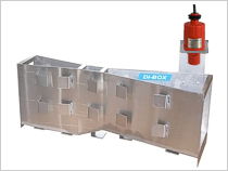
The subject of our offer is a Parshall flume intended for measuring momentary and total flow of the liquid in gravitational channels, with the use of an ultrasonic flow meter FLOWBOX. Upon request, it’s also possible to carry out pre-investment technical consulting, as well as subsequent installation, launching* and protocol-based delivery of flow meter for the use. We also sell individual elements of the measuring set manufactured by us (e.g. only Parshall flume or only flow meter FLOWBOX).
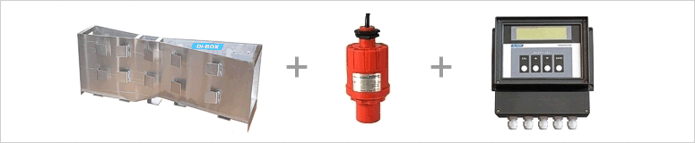
The liquid flow rate measurement with Parshall flume and water rise method in rectangular channels is based on the actual liquid level measured by the ultrasonic sensor (radar sensor, optional) at the hydraulic structure converted into the value of flow ratio by the measuring transmitter.
The basic condition to apply the method is to provide, undisturbed and laminar flow in a measuring flume and free outflow of liquid from the measuring flume.
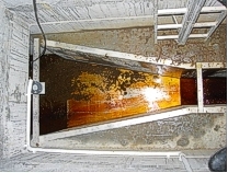
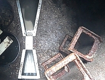
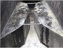
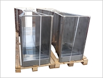
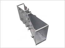
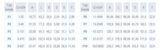
Parshall flumes in accordance with ISO 9826 data sheet are intended for measurement of volumetric flow rate in rectangular channels with gravity flow. The flumes are made of stainless steel or PVC sheets and enable measurements within the range specified in the table below.
The flume is embedded in concrete in a rectangular channel with subcritical flow. The conditions can be obtained by maintaining a specific gradient and minimum inlet and outlet channel length. The measurement in lower range for a specific flume type will be encumbered with a significant error.

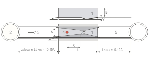
Legend:
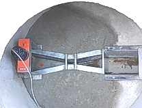
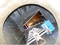
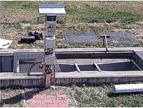
1 - Parshall flume
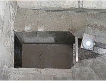
2 - Well
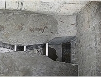
3 - Inlet channel
4 - Ultrasonic level sensor
5 - Outlet channel
Exemplary Parshall flumes instalations------------